


Calculation of the relationship between use and reliability of tantalum capacitor
Tantalum metal is a kind of rare high density heavy metal, which has strange characteristics. In acid resistance, it almost does not react with any highly corrosive acid. Therefore, the tantalum capacitor produced by it has high stability and can keep its performance unchanged for decades. Therefore, in the initial stage of tantalum capacitor, it is a special high reliability capacitor
In addition, it is a very easy to oxidize metal. It can react with oxygen at room temperature. This phenomenon basically goes against the basic chemical law. Metals prone to oxidation reaction are generally not resistant to acid corrosion. However, tantalum is an example. Therefore, the tantalum capacitor produced must have very special performance, high stability and long life, High temperature performance, the highest volume ratio. Of course, there are high cost and too complex production technology
On the premise of outstanding advantages, tantalum capacitors also have fatal weaknesses. Compared with other capacitors, tantalum capacitors can't withstand high reverse voltage. This is the same as genius artists; they have extraordinary talents, but also have disadvantages far inferior to human beings... If the use method and conditions are appropriate, tantalum capacitors can not withstand high reverse voltage, Tantalum capacitors still have the highest reliability. This is the fundamental reason why they have become the first choice in the high reliability industry
Tantalum capacitors are not only criticized, but also praised. They may be devices that are still in good condition after decades of use, or they may suddenly fail during power on test due to other factors
In fact, the advantages of tantalum capacitors can be fully developed through proper use and design, provided that we users have a sufficient understanding of its advantages and disadvantages, and nip the problem in the bud when selecting types and designing circuits
I often see that when many institutes carry out the research and development of electronic machines, they just pass the actual power on test, and then through the load experiments under various conditions. However, when mass production occurs, problems occur frequently. When problems occur, they just search for some process details, However, there is no objective evaluation on the reliability of the system design. The development and verification based on facts is justifiable, but a reasonable design needs not only small batch of actual verification, but also scientific calculation verification. Because a circuit with insufficient design reliability may be verified by small batch of experiments, However, there will be problems in mass production. There can only be one way to prevent this problem; the design that can pass the reliability calculation + the design verified by the actual experiment. From a more scientific point of view, we obviously ignore the design reliability calculation verification
We must realize that the reliability should be designed first and not others, and the reliability of design must be verified by reliability calculation and actual load test
When the experience can be verified by mathematics, the experience can be called science. Otherwise, it is only the experience with fuzzy property. For chip tantalum capacitor, its reliability can be calculated in advance. We can't wait for the problems in experiment to find out the design problems. This is an unscientific behavior of seeking fish from wood
The reliability calculation of tantalum capacitors used in electronic circuits under different service conditions is shown in the following specific instructions. As long as these are taken into account sufficiently, the reliability of the whole machine with respect to the reliability of the capacitor part can be guaranteed. For the electronic whole machine, the most easily failed part is the power supply part, and for the power supply part, the most vulnerable component is the capacitor, By solving the failure problem of capacitor, the reliability design of the whole machine can be raised to a higher level
The following instructions will tell tantalum capacitor users that the reliability of tantalum capacitors in your circuit and the reliability of your designed equipment can reach a high standard if the following conditions are followed;
1. Reliability calculation of whole system and subsystem [basis]
The reliability design of different types of electronic machines varies greatly due to their uses. For example, personal IT products can guarantee no major problems within three years. The n0kia personal products with good quality reflect that they are more durable because of the high reliability standards, Because of the wide range of working environment, the robustness must be considered when designing reliability. Therefore, the reliability design of electronic products for different purposes depends on its use conditions and environmental restrictions. We can not ask that the reliability level of a personal IT product working indoors be raised to several decades, It's a waste. Similarly, you can't design the reliability of airplanes to the level of personal IT products. It's a crime. However, the reliability of an electronic device is designed first, and is not determined by simple production, There must be clear and quantifiable enough perfect parameter index. The specific standard is actually the agreement index of each company or user. There is basically no fixed value that can be followed
However, the reliability of electronic equipment is based on the reliability of circuit design and the level of process control. Therefore, the reliability of the whole machine can be decomposed into many specific standards
For the whole electronic machine using tantalum capacitor, the reliability of its components can be calculated, so the reliability of the sub circuit can be calculated. It is worth noting that the reliability of the whole machine must be based on the electricity with the lowest reliability
2. Reliability calculation under different service temperature
The leakage current of tantalum capacitor increases with the increase of temperature. When working between 85 ℃ and 125 ℃, the maximum operating voltage Vmax must be derated, and the appropriate derating range can be adjusted from
In the following formula:
Vmax=( 1-(T-85)/125)×VR
Here: t is the required operating temperature
VR is the rated voltage
It should be noted that the above formula is only applicable to high impedance discharge circuit. At the same time, the above formula does not consider the influence of AC component and surge. Therefore, when the service temperature is higher, a larger derating voltage must be used to work stably and reliably
3. Reliability calculation under different voltage
The reliability of solid tantalum capacitors is greatly affected by environmental conditions. For example: temperature, humidity, shock, vibration, mechanical stress and electric field strength, including applied voltage, ripple current, instantaneous current and voltage, and frequency.
The reliability of the whole electronic machine is based on the higher reliability of the electronic components. Therefore, the failure rate of the components used must be higher than the failure rate requirements of the whole machine before using and selecting the type. The field failure rate [MTBF] of solid tantalum capacitor can be calculated from the following expression:
MTBF=λ0(V/V0)3×2(T-T0)/10
here:
MTBF: failure rate under actual working conditions
Maximum allowable temperature T: 85 ℃
5: Actual voltage
λ 0: failure rate under rated load (1% / 1000h)
T0: actual use temperature
V0: rated voltage
Test conditions:
Temperature: 85 ℃
Voltage: rated voltage
Rs: 3 Ω [required line protection resistance]
The above formula shows that the over high temperature and voltage have a great influence on the reliability of the product. Under the condition of the maximum operating temperature and working voltage, the product with higher rated voltage should be selected as far as possible to meet the requirements.
4. Reliability calculation in filter circuit
If the ripple current is applied to the capacitor, Joule heat (power loss) will be generated in the capacitor, so the ripple current will affect the reliability of the capacitor.
(1) Power loss
The actual power loss of capacitor through AC ripple can be calculated by the following formula:
P=I2 × ESR……………….Formula 1
here:
P: Power loss (Watts)
1: Ripple current (Amperes)
ESR: equivalent series resistance (Ω)
The heat dissipation capacity of different shell products is different due to their different volumes. Therefore, the maximum heating power generated by the allowable AC ripple to maintain heat balance is shown in Table 1 below;
![]()
Table 1 maximum allowable power loss
(2) Ripple current
Using the maximum power loss in Table 1, the maximum ripple current (arms) can be calculated using the following formula:
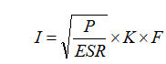 ………………….Formula 2
Here: it is also necessary to consider the actual operating temperature of the capacitor at this time. The temperature derating factors under different operating temperatures are shown in the table below;
K:Temperature derating factor . Table 2
F: Frequency derating factor Table 3
ESR:DC series resistance reference rating
Table 2: temperature derating factor K
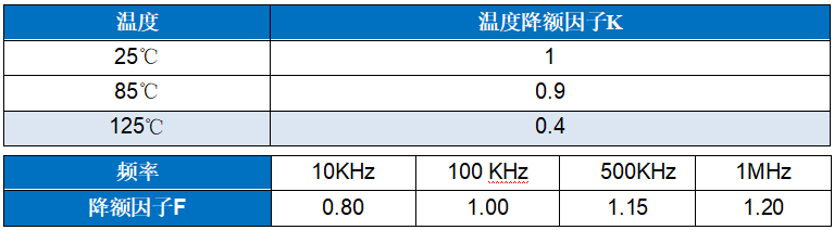
In addition, it can not be ignored that when used in the filter circuit, the actual working frequency must be considered, and the derating amplitude under different working frequency will be different
The ripple voltage e is calculated by formula 3
E=Z×I………………………….. Formula 3
here:
E: Ripple voltage
Z: Impedance at specific frequency
It can be seen from the above calculation that the capacitors working at different operating frequencies have different AC ripple values due to the constant impedance. If the AC ripple value in the circuit exceeds the allowable safe bearing range of the capacitor, the capacitor will have thermal breakdown after working for a period of time due to the accumulated heat exceeding the heat dissipation capacity
5. Reliability calculation of discharge circuit under different power
If the capacity of the circuit capacitor can determine the maximum instantaneous discharge power of the circuit, the rated voltage and capacity of the capacitor can be selected according to the following calculation when the power requirement is certain; when the input power is p, the capacity of the energy storage capacitor is C, and the voltage at both ends is U1, then the energy stored in the capacitor isW1=C(U12)/2,
When the input power is off, after time t, the voltage at both ends of the capacitor is U2, and the remaining energy of the capacitor isW2=C(U22)/2,
In this process, the energy released by the energy storage capacitorW=W1-W2=C(U12-U22)/2,
It should be equal to the energy required for the circuit to function properly
W = Pt, (i.e. input power times time)
So there are
C(U12-U22)/2=Pt,
Thus, the minimum capacitance required for the circuit holding time t is obtained
C=2Pt/(U12-U22).
In practical application, U2 is the lowest input voltage for the circuit to work normally
give an example:
If the input voltage of the circuit is 28V (U1), the input power is 30W (P), and the minimum input voltage that can work normally is 18V (U2),When the input power supply is powered down for 50 ms (T), the circuit can still work, and the minimum capacitance of the required energy storage capacitor is
C=2 Pt/(U12-U22)
=2*30*50/(282-182)
=3000/(784-324)
=6.522mF=6522mF
An energy storage capacitor used in the front end of the power supply circuit has an input voltage of 50V. When the power supply is short, the capacitor starts to provide energy for the subsequent circuit When 75W, the voltage must not be lower than 18V. Please calculate the required capacitance.
This circuit also requires an accurate loop resistance. The loop resistance determines the capacity of the capacitor required.
The conversion formula of each parameter performance in this circuit is as follows;
C=R*PT*T/U1-U2
Where;
C. Required capacitance
R. Total loop resistance
PT; power to be maintained by loop
T. Loop power hold time
U1; input voltage
U2; voltage that can maintain certain power and discharge time
When the capacitor is used in the discharge circuit, the maximum DC discharge current I that the capacitor can bear;
I=UR/(1+ESR)
For high power discharge circuit, the capacitor with better actual withstand voltage and lower ESR must be selected
7. Reliability calculation under different operating frequencies
There is resistance loss in all capacitors. It includes resistance and contact resistance, dielectric resistance and loop resistance. To represent the effect of these losses, they are referred to as equivalent series ESRs of capacitors. ESR is related to frequency and can be obtained by using the following relationship:
ESR= tgδ/2πfC
Here: F is the frequency, in Hz, and C is the capacity of the capacitor in farads. The ESR test conditions are: 20 ℃ and 100kHz
Because the ESR of the capacitor tends to increase or decrease under different frequencies, and the change of ESR will directly lead to the different heating capacity of the capacitor during filtering, When the frequency is constant, we can calculate the capacity and the actual impedance of the capacitor according to the above formula. In this way, we can calculate the appropriate frequency limit of the capacitor according to the known basic performance of the capacitor, We can know whether the actual capacity of the capacitor can meet the requirements of filtering performance at a certain frequency
8. Calculate the maximum output current of capacitor in filter circuit;
8.1. Capacitor buck half wave rectifier circuit
When half wave rectification is adopted for capacitor step-down power supply, the current (average value) per micro capacitance is: (SI unit)
I(AV) = 0.44*V/Zc = 0.44*220*2*Pi*f*C = 0.44*220*2*3.14*50*C = 30000C
= 30000*0.000001 = 0.03A = 30mA
8.2. If the bridge rectifier is used, the double current (average value) can be obtained as follows:
I(AV) = 0.89*V/Zc = 0.89*220*2*Pi*f*C = 0.89*220*2*3.14*50*C = 60000C
= 60000*0.000001 = 0.06A = 60mA
When using capacitor buck bridge rectifier circuit, the following matters should be paid attention to:
1. It is not isolated from 220 V AC high voltage, please pay attention to safety and avoid electric shock!
2. The current limiting capacitor must be connected to the live wire, and the withstand voltage should be large enough (more than 400V), and a series of surge protection and safety resistance and parallel discharge resistance should be added
3. Pay attention to the power consumption of the zener diode. It is strictly forbidden to disconnect the zener diode
The above calculation method is the basic knowledge for capacitor design